These days there is a significant demand for accurate 3D models of compact objects due to their different applications in numerous fields, including prototyping, simulation, and design. However, the critical question is how to create highly accurate 3D models efficiently. LAB University of Applied Sciences developed an efficient and time-saving method by integrating reverse engineering with a digital microscope and implementing SolidWorks software and Microsoft Visual Basic for Applications (VBA). This technique allows anyone needing highly precise 3D models to create them easily.
Creating 3D models of the commercial resolvers
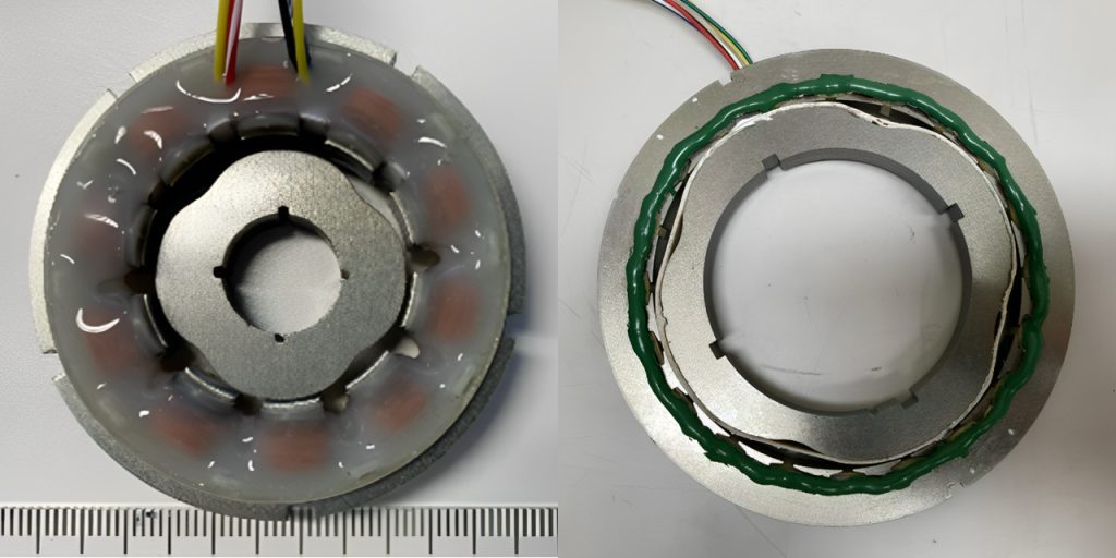
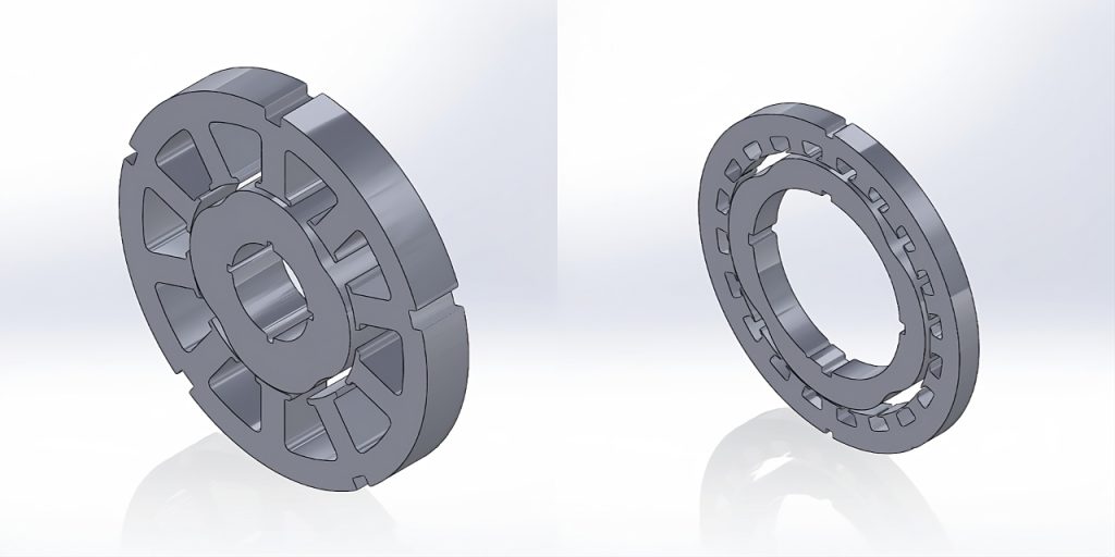
Two commercial resolvers were investigated in the joint LAB UAS and LUT University project Resolvo. Resolver is a sensor that measures the position and speed of moving electrical machines. The primary objective of this study was to produce a precise replication of the steel geometry, including the stators and rotors, within the SolidWorks software, enabling subsequent Finite Element Analysis (FEA) of these selected resolvers.
Link to the website of Resolvo project.

The SmartScope FLASH 200 digital microscope system was utilized to capture the geometry of the resolvers (OGP – Optical Gaging Products 2015). Coupled with 2D scanning capabilities, it opens possibilities for reverse engineering. In the case of creating 3D models of commercial resolvers, the high level of accuracy plays a critical role in ensuring the precision and reliability of future models. It, therefore, affects the result of any subsequent analysis.
Being familiar with the SmartScope FLASH 200 and its software was necessary. Success came from several test scans that confirmed the system’s effectiveness. Afterward, the focus shifted to scanning the resolvers.
An essential aspect of this project was developing a highly efficient method for post-processing the scanned data which existed in DXF file format within SolidWorks. Several concepts were explored, with the final choice being the implementation of macros. This, however, required some skills in scripting, and therefore it prompted the decision to dive into the field of SolidWorks Application Programming Interface (API). As a result, three programs were made, offering users the flexibility to apply the most efficient code in various scenarios.
The 3D modeling process within SolidWorks demanded the exploration of tools not typically used in conventional modeling. Significant attention was paid to tools for creating different spline shapes, such as “Fit Spline” and “Spline through XYZ points”. Furthermore, taking the 2D nature of the scanned data into account, tools that enable the transformation of complex 2D shapes into 3D models, like “Boundary Boss/Base” and “Boundary Cut”, were carefully studied.

In general, this work’s value lies in its wide range of applications in reverse engineering. The precise 3D modeling technique that has been developed can increase the efficiency and accuracy of processes across various areas from product design to prototyping.
Authors
Sergei Shabanov is a Mechanical Engineering student at LAB University of Applied Sciences. His primary work has focused on exploring the capabilities of the digital microscope for 2D scanning and subsequent post-processing of scanned data via SolidWorks software.
Eero Scherman is a Senior Lecturer in Mechanical Engineering at LAB University of Applied Sciences. His research interests focus on mechanical engineering, particularly on the manufacturing aspects of rotating electrical machines.
References
OGP – Optical Gaging Products. 2015. OGP SmartScope® Flash™ 200 with ZONE3®. Cited 28 Sep 2023. Available at https://www.youtube.com/watch?v=CRSWW9O5v7Y
Links
Link 1. LAB University of Applied Sciences. 2022. Resolvo- Innovaation kaupallistaminen. Cited 14 Sep 2023. Available at https://lab.fi/en/project/resolvo-innovaation-kaupallistaminen


